Behind the scenes
In order to implement this service, I had to do some theoretical work and spent many hours scribbling on paper. The intention of this page is to provide insight into thoughts, considerations and work I did to make this project happen.
Prerequisites Preliminary considerations
The German Naval Grid was developed to be plotted on charts and there is no evidence that U-boat navigators converted mathematically during the war. That said, the grid follows general rules, which make solving the internal structure of uncertain squares and the mathematical conversion of grid positions to geographic coordinates possible. The following paragraphs discuss the grid and the geographic coordinate system .
-
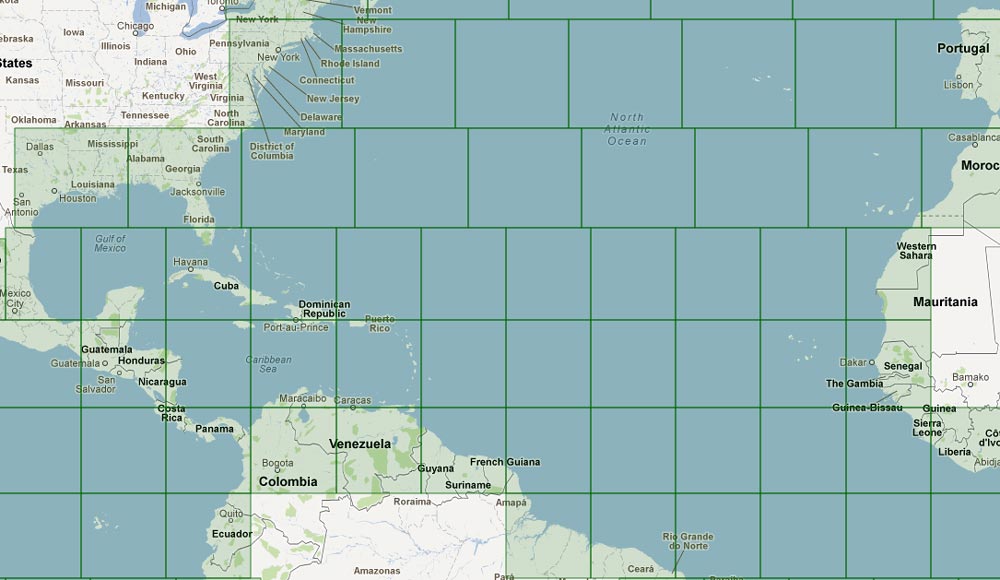
The German Naval Grid was laid out on a Mercator projection chart. A very useful property of the Mercator projection is that all longitudinal lines are parallel to the prime meridian, while all latitudinal lines are parallel to the Equator. Grid squares appear as perfect rectangles on a Mercator projection chart. The upper and lower edges are parallel to the equator, while the left and right edges are parallel to the prime meridian. All interior angles are right angles. When plotted on the curved surface of the earth, these squares look like pillows (isosceles trapezoids with curved edges), with the sides bent along the curvature of the surface. The upper and lower edge lengths differ depending on the distance from the equator. The edge closer to the pole is shorter than the edge closer to the Equator, because all longitudinal lines meet at the poles where the distance between them decreases to zero. The left and right sides of a grid square are always of the same length, because the latitudinal lines of the geographic coordinate system are a constant distance from one another.
-
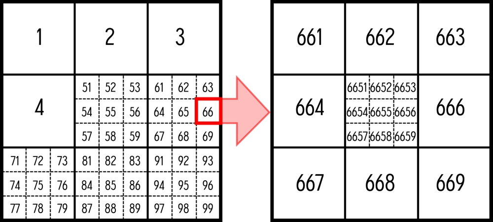
The German Naval Grid consists of 536 large squares, 465 of which are "regular". Regular squares are perfect rectangles (almost "squares") which can be split into 9 sub squares, each of which can be split into 9 sub squares. Then again and again making a total of 81 by 81 "small squares" (Kleinquadrat) in one "large square" (Großquadrat). Each sub square is identified by the identifier (ID) of the large square (usually referred to as "bigram") and its number within the matrix. The numbering follows the frequently mentioned number pad of a telephone, where 1, 2 and 3 are in the first row and 7, 8, 9 are in the last. For example, BC contains sub squares BC1 to BC9. BC6 contains the sub squares BC61 to BC69 and so on.
-
The 71 remaining large squares are "irregular". Their internal structure does not follow the general pattern of regular squares. There are several types of irregular squares, which can be classified into four groups:
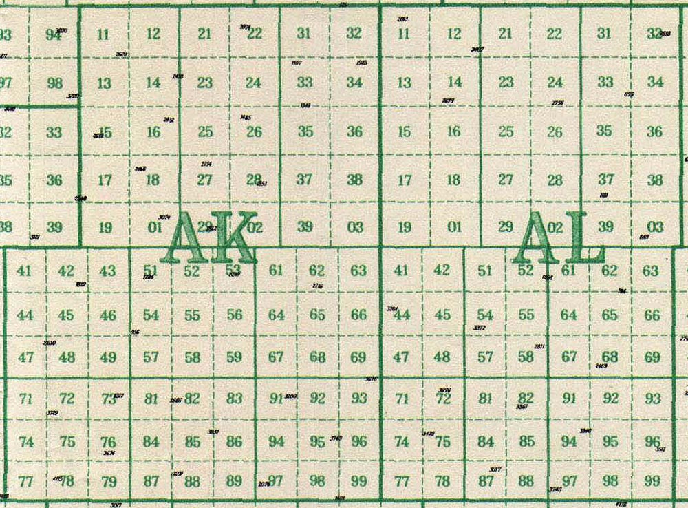
- Two-by-five squares contain 10 regular sub squares grouped horizontally in two rows and five columns or vertically in five rows and two columns. The tenth sub square has an unusual ID, which is not the ID of the parent square followed by the consecutive number of the sub square, but a leading zero followed by the parent square ID. For example, AK1 consists of the sub squares AK11 to AK19 plus AK01 while AK2 consists of the sub squares AK21 to AK29 plus AK02.
- Two-by-four squares are similar to two-by-five squares, except that they are missing the ninth and tenth sub squares.
- Partial squares are perfect rectangles like regular squares; however they do not follow the nine by nine matrix, but leave out some rows and or columns. The internal numbering follows the system of regular squares, just skipping the numbers of the missing rows and or columns.
- Polygonal squares have no regular shape. They may but do not necessarily contain nine sub squares, which can be of any mentioned type, even polygonal.
-
On Mercator charts, the apparent size of squares differs depending on their location. Squares close to the equator appear small, while squares close to the poles appear much larger. In fact, all regular squares are roughly the same size on the earth's surface. The difference in appearance is caused by the distortion due to the Mercator projection.
-
Because the designers of the grid intended to keep the actual size of small squares constant at about six by six nautical miles, most large squares are about 486 x 486 nautical miles. Although these squares appear bigger towards the poles on a Mercator chart, horizontally adjacent squares are usually congruent, or in other words, identical in size.
-
Large squares are usually located in rows along constant latitudes. As a result adjacent squares have identical latitudes.
-
Analysis of the German Naval Grid suggests the following general rules, which are fully supported by all known squares.
- When squares overlap, one or the other is cut off to make the squares fit. There are no overlapping/ambiguous squares.
- Different scaling within large squares is only used to adjust for the Mercator projection distortion and not to make cut off squares fit.
- When squares are cut from top to bottom, first squares in a series are cut on the left.
- Middle squares in a series that are cut all the way from top to bottom are cut on the right.
- Last squares in a series that are cut all the way from top to bottom are cut on the right.
-
The geographic coordinate system is based on horizontal and vertical angles. The latitude is defined by an angle of 0° at the equator and up to 90° at the poles. Latitudes between the Equator and North Pole are positive, while latitudes between the Equator and South Pole are negative. Longitudes are defined by an angle of plus or minus 180° from the Greenwich meridian to the antimeridian. Greenwich in England is exactly at 0°, while the exact opposite meridian on the other side of the world is at 180°.
Data Analysis What data we're dealing with
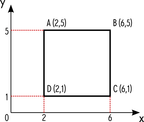
Since all regular—and many irregular—squares are perfect rectangles, they can be fully described by exactly two diagonally opposite corner coordinates. If the upper left and the lower right coordinates of a rectangle are known, one can determine the missing ones by switching the x and y values of the known coordinates. For example, the upper right coordinate has exactly the same latitude as the upper left and the same longitude as the lower right coordinate. Any rectangular square—no matter if regular or irregular—is defined by its name and the upper left and lower right coordinate, while any polygonal square is defined by its name and all its corner coordinates. This reduces the required stored data by half for rectangular squares.
A regular square's sub squares can be easily calculated by dividing the side lengths by 3 to get a three by three matrix. Two-by-five and two-by-four squares allow a similar calculation by creating a two by five or two by four matrix respectively. Partial squares can be viewed as regular squares with missing rows or columns. As a result, their sub squares can be calculated as for regular squares, but skipping the non-existing rows or columns. Polygonal squares' sub squares can not be calculated, but need to be stored as for large squares. If a sub square is a polygon, its sub squares must be stored individually. The reduction of stored data for regular squares is expected to more or less offset by the increased data that must be stored for polygonal squares.
Most regular squares are congruent, particularly if they are on the same latitude. There are six rows of regular squares spanning the globe above and below the equator. Almost all are regular and congruent. This facilitates reducing stored data immensely by the grouping of squares into rows or columns. A group of squares is described by the coordinates of the first square and a list of all contained squares' names and their offset within a row (or column). As a result the coordinates of any square in the group can be calculated with a minimum of data by multiplying the first square's coordinates with the offset of the requested square name. For example, AA, AB, AC and AT are congruent squares in a row and can be grouped into a series which is fully defined by AA's two coordinates and the list of containing square names:
- Upper left coordinate of AA
- Lower right coordinate of AA
- Contained squares: 0 ⇒ AA, 1 ⇒ AB, 2 ⇒ AC, 3 ⇒ AT
Calculations How to calculate the squares
The calculation of sub squares within rectangular squares is easy in theory. You start with two corner coordinates and can get the other two by exchanging latitude and longitude as explained earlier. With the resulting base coordinates you can get the width and height of the square in degrees. If you divide these values by 3 (or 2 or 5 depending on the type of square) you get the width and height of any of the congruent sub squares. With this information you can calculate the sub square's corner coordinates by multiplying the base coordinate of the parent square with the sub square's offset in the matrix in both horizontal and vertical directions.
Unfortunately it is not that simple. Because of the geographic coordinate system, you cannot calculate with 360 degrees horizontally and 180 degrees vertically but must deal with plus and minus 90 degrees for latitude and plus and minus 180 degrees for longitude. If a square is positioned over the prime meridian and has edges on both sides of it, everything is fine. But if a square is positioned across the antimeridian, the coordinates of the left edge are positive while the ones of the right edge are negative.
Another issue is the calculation of the real size of the square in nautical miles. The distance between two adjacent longitudinal degrees decreases with an increasing distance from the Equator. On the Equator two adjacent longitudinal degrees are about 60 NM apart, in New York City the distance is about 45.55 NM and 0 NM at the poles.
To deal with the issues above with a single solution, I used formulae to calculate rhumb lines provided by Chris Veness. Unlike great circle lines (or orthodromes), a rhumb line (or loxodrome) crosses all meridians of longitude at the same angle. In a Mercator projection a rhumb line appears as a straight line. You can calculate the exact distance (in nautical miles) and bearing between two points on a rhumb line, no matter how close they are to the poles. You can also calculate a destination point on a rhumb line with given start point, distance and bearing. It is also possible to calculate the exact mid point between two coordinates on a rhumb line. Since the German Naval Grid is based in a Mercator projection, each square's edges are rhumb lines. Since these formulae can handle the meridian, antimeridian and the Equator problem, they are very suitable for these calculations. In addition they provide an easy way of calculating exact edge lengths of squares on the earth's surface and to calculate the center coordinate of any square.
The calculation of squares within a group works exact the same way as for sub squares. It is even easier, because there is no matrix to respect, but always exactly one row or column of squares. The rhumb line formulae are used here as well.
The Repository How to save the data
The fastest way for a program to convert a square reference into a center coordinate is to store all square references together with their center coordinates in a lookup table. Looking up an ID in a table is always faster than any calculation, but requires the storage of a lot of data. To display the corner coordinates, these must be added to the table, as well as the size.
Assuming that all 536 large squares are regular squares with each 9 sub squares, with each sub square having 9 sub squares and so on, we will end up with storing data for around 4 million squares. The most irregular square is BG, having 20 corners, which requires at least 20 columns for corner coordinates. Since we want to show the coordinates in different formats, we need to store latitude and longitude separately, doubling the amount of required columns.
As discussed above, the approach for this program is based on calculations rather than looking up data in a table. This will slow the response, because everything will be calculated on demand, but will decrease the amount of stored data.
Using this approach, it is not necessary to store width and height for each square, because this can be calculated from the corner coordinates; the same applies for the center coordinate. This reduces the number of columns in our lookup table. For regular squares we can also omit two of the four corner coordinates, since they can be calculated from the remaining two also reducing the number of columns. Most importantly, for regular squares, it is not necessary to store all the sub squares, because we can calculate them from the large square they are in. This reduces the number of rows from 4 million to just a couple of hundred.
If we group adjacent congruent regular large squares, we can further reduce the number of rows in our table. I was able to group 461 regular large squares into only 67 groups, 4 large squares can not be placed in a group.
In order to be able to release the core library with all calculations and all required square data, I decided to not to use a database, but to store the data in Comma Separated Value (CSV) files, delivered together with the code files.
Regular Large Squares
Almost all regular large squares can be put into groups of adjacent congruent squares. These groups always have a horizontal orientation. As a result, the CSV file for these squares thus contains only groups. Some large squares can not be placed in a group, but for purposes of the program, can be considered as a group of only one square.
The CSV file for regular large squares contains 6 columns:
- ID, which is an arbitrary id for each group, which can be either a number or a string. I chose to take the id of the first and last square in each group for convenience during debugging.
- LATITUDE1, the latitude of the upper left corner coordinate of the first square in this group
- LONGITUDE1, the longitude of the upper left corner coordinate of the first square in this group
- LATITUDE2, the latitude of the lower right corner coordinate of the first square in this group
- LONGITUDE2, the longitude of the lower right corner coordinate of the first square in this group
- CONTAINED SQUARES, an ordered, comma separated list of the ids of all squares in the group
| ID | LATITUDE1 | LONGITUDE1 | LATITUDE2 | LONGITUDE2 | CONTAINED SQUARES |
|---|---|---|---|---|---|
| ÄJÄF | 85.2 | -76 | 77.1 | -35.5 | ÄJ,ÄH,ÄG,ÄF |
| CG | 42.9 | -15.1 | 34.8 | -4.3 | CG |
| PBEW | 10.5 | -100.9 | 2.4 | -92.8 | PB,PC,EL,EM,EN,EO,EP,EQ,ER,ES,ET,EU,EV,EW |
| WWHN | -54.3 | -92.2 | -62.4 | -76 | WW,HH,HJ,HK,HL,HM,HN |
| XAXE | 82.4 | 86 | 74.3 | 113 | XA,XC,XE |
ID;LATITUDE1;LONGITUDE1;LATITUDE2;LONGITUDE2;CONTAINED SQUARES
ÄJÄF;85.2;-76;77.1;-35.5;ÄJ,ÄH,ÄG,ÄF
CG;42.9;-15.1;34.8;-4.3;CG
PBEW;10.5;-100.9;2.4;-92.8;PB,PC,EL,EM,EN,EO,EP,EQ,ER,ES,ET,EU,EV,EW
WWHN;-54.3;-92.2;-62.4;-76;WW,HH,HJ,HK,HL,HM,HN
XAXE;82.4;86;74.3;113;XA,XC,XE
Partial Large Squares
Partial large squares are regular squares where rows or columns are missing. Although these are considered irregular, they can be calculated and stored like regular squares. The 14 large partial squares can be put into 10 groups of adjacent congruent squares saving 4 rows. These groups all have a vertical orientation. Squares which can not be grouped can be entered as a group of only one square.
The CSV file for partial large squares contains 7 columns:
- ID, which is an arbitrary id for each group, which can be either a number or a string. I chose to take the id of the first and last square in each group for convenience during debugging.
- LATITUDE1, the latitude of the upper left corner coordinate of the first square in this group
- LONGITUDE1, the longitude of the upper left corner coordinate of the first square in this group
- LATITUDE2, the latitude of the lower right corner coordinate of the first square in this group
- LONGITUDE2, the longitude of the lower right corner coordinate of the first square in this group
- MATRIX, the binary representation of the existing rows and columns. The first three digits represent the columns, while the last three digits represent the rows. E.g. 100111 means that the square contains the first column only, but all three rows. The second and third column is missing.
- CONTAINED SQUARES, an ordered, comma separated list of the ids of all squares in the group
| ID | LATITUDE1 | LONGITUDE1 | LATITUDE2 | LONGITUDE2 | MATRIX | CONTAINED SQUARES |
|---|---|---|---|---|---|---|
| OFOT | 41.9 | 167 | 33.8 | 170.6 | 100111 | OF,OT |
| URVF | -22.9 | 167 | -31 | 170.6 | 100111 | UR,VF |
| NLNU | 58.1 | 167 | 50 | 176 | 110111 | NL,NU |
| JJ | -38.1 | 17.3 | -46.2 | 24.5 | 110111 | JJ |
| XJ | 82.4 | 167 | 74.3 | 176 | 100111 | XJ |
ID;LATITUDE1;LONGITUDE1;LATITUDE2;LONGITUDE2;MATRIX;CONTAINED SQUARES
OFOT;41.9;167;33.8;170.6;100111;OF,OT
URVF;-22.9;167;-31;170.6;100111;UR,VF
NLNU;58.1;167;50;176;110111;NL,NU
JJ;-38.1;17.3;-46.2;24.5;110111;JJ
XJ;82.4;167;74.3;176;100111;XJ
Rectangular Irregular Squares
Rectangular irregular squares don't follow the established rules for their internal structure. Their sub squares are incalculable. This file contains not only large squares, but also irregular sub squares which are rectangular. They are grouped, but the group's orientation may be either vertical or horizontal. Squares which can not be grouped are entered as a group of only one square.
The CSV file for rectangular irregular squares contains 7 columns:
- ID, which is an arbitrary id for each group, which can be either a number or a string. I chose to take the id of the first and last square in each group for convenience during debugging.
- LATITUDE1, the latitude of the upper left corner coordinate of the first square in this group
- LONGITUDE1, the longitude of the upper left corner coordinate of the first square in this group
- LATITUDE2, the latitude of the lower right corner coordinate of the first square in this group
- LONGITUDE2, the longitude of the lower right corner coordinate of the first square in this group
- ORIENTATION, the letter
vfor vertical orhfor horizontal. - CONTAINED SQUARES, an ordered, comma separated list of the ids of all squares in the group
| ID | LATITUDE1 | LONGITUDE1 | LATITUDE2 | LONGITUDE2 | ORIENTATION | CONTAINED SQUARES |
|---|---|---|---|---|---|---|
| AR | 69 | 70.25 | 60.9 | 86 | v | AR |
| AS | 77.1 | 74 | 69 | 86 | v | AS |
| BK6 | 51 | 47 | 50 | 51.5 | h | BK6 |
| BK7 | 49.2 | 36.5 | 47.4 | 42.5 | h | BK7 |
| BK56BK66 | 50.1 | 45.5 | 50 | 47 | h | BK56,BK64,BK65,BK66 |
ID;LATITUDE1;LONGITUDE1;LATITUDE2;LONGITUDE2;ORIENTATION;CONTAINED SQUARES
AR;69;70.25;60.9;86;v;AR
AS;77.1;74;69;86;v;AS
BK7;49.2;36.5;47.4;42.5;h;BK7
BK6;51;47;50;51.5;h;BK6
BK56BK66;50.1;45.5;50;47;h;BK56,BK64,BK65,BK66
Polygonal Squares
Polygonal squares don't follow any general scheme for internal structure. Their sub squares are incalculable. This file contains not only large squares, but also sub squares, which are polygonal. They can not be grouped and are always stored individually. Some of these squares contain up to 20 corner coordinates. For squares with fewer corners, the corresponding columns are left empty.
The CSV file for polygonal squares contains 41 columns:
- ID, which is an arbitrary id for each group, which can be either a number or a string. I chose to take the id of the first and last square in each group for convenience during debugging.
- LATITUDE1, the latitude of the most top left corner coordinate
- LONGITUDE1, the longitude of the most top left corner coordinate
- ...
- LATITUDE20, the latitude of the last corner coordinate if existing
- LONGITUDE20, the longitude of the last corner coordinate if existing
| ID | LATITUDE1 | LONGITUDE1 | LATITUDE2 | LONGITUDE2 | LATITUDE3 | LONGITUDE3 | ... |
|---|---|---|---|---|---|---|---|
| AO | 60.9 | 7.7 | 60.9 | 31.1 | 59.1 | 31.1 | ... |
| AO7 | 56.4 | 9.5 | 56.4 | 14 | 53.7 | 14 | ... |
| AO8 | 56.4 | 14 | 56.4 | 17 | 52.8 | 17 | ... |
| AP | 60.9 | 31.1 | 60.9 | 40.1 | 59.1 | 40.1 | ... |
| AQ | 60.9 | 40.1 | 60.9 | 58.1 | 56.4 | 58.1 | ... |
ID;LATITUDE1;LONGITUDE1;LATITUDE2;LONGITUDE2;LATITUDE3;LONGITUDE3;...
AO;60.9;7.7;60.9;31.1;59.1;31.1;...
AO7;56.4;9.5;56.4;14;53.7;14;...
AO8;56.4;14;56.4;17;52.8;17;...
AP;60.9;31.1;60.9;40.1;59.1;40.1;...
AQ;60.9;40.1;60.9;58.1;56.4;58.1;...
Two-by-Five Squares
Two-by-five squares are similar to regular squares. Their internal structure follows different rules. They can be similarly grouped. The orientation of the group as well as the orientation of the square (2 by 5 or 5 by 2) must be stored as well.
The CSV file for two-by-five squares contains 7 columns:
- ID, which is an arbitrary id for each group, which can be either a number or a string. I chose to take the id of the first and last square in each group for convenience during debugging.
- LATITUDE1, the latitude of the upper left corner coordinate of the first square in this group
- LONGITUDE1, the longitude of the upper left corner coordinate of the first square in this group
- LATITUDE2, the latitude of the lower right corner coordinate of the first square in this group
- LONGITUDE2, the longitude of the lower right corner coordinate of the first square in this group
- SQUARE ORIENTATION, the letter
vfor vertical orhfor horizontal. - GROUP ORIENTATION, the letter
vfor vertical orhfor horizontal. - CONTAINED SQUARES, an ordered, comma separated list of the ids of all squares in the group
| ID | LATITUDE1 | LONGITUDE1 | LATITUDE2 | LONGITUDE2 | SQUARE ORIENTATION | GROUP ORIENTATION | CONTAINED SQUARES |
|---|---|---|---|---|---|---|---|
| ÄA1ÄA3 | 60.9 | -71.5 | 59.1 | -62.5 | h | h | ÄA1,ÄA2,ÄA3 |
| AN2 | 60.9 | -1.3 | 59.1 | 7.7 | h | h | AN2 |
| AN9 | 56.4 | 6.5 | 51.9 | 9.5 | v | h | AN9 |
| BH4 | 51.9 | 6.5 | 47.4 | 9.5 | v | h | BH4 |
| BH7 | 47.4 | 11 | 45.6 | 18.5 | h | h | BH7 |
ID;LATITUDE1;LONGITUDE1;LATITUDE2;LONGITUDE2;SQUARE ORIENTATION;GROUP ORIENTATION;CONTAINED SQUARES
ÄA1ÄA3;60.9;-71.5;59.1;-62.5;h;h;ÄA1,ÄA2,ÄA3
AN2;60.9;-1.3;59.1;7.7;h;h;AN2
AN9;56.4;6.5;51.9;9.5;v;h;AN9
BH4;51.9;6.5;47.4;9.5;v;h;BH4
BH7;47.4;11;45.6;18.5;h;h;BH7
Partial Squares
Partial squares are regular squares where rows or columns are missing. Although these are considered irregular, they can be calculated and stored like regular squares. They can be grouped in both horizontal and vertical orientation. Squares which can not be grouped can be added as a group of one square. This file contains all sub squares that are either regular or partial.
The CSV file for partial squares contains 8 columns:
- ID, which is an arbitrary id for each group, which can be either a number or a string. I chose to take the id of the first and last square in each group for convenience during debugging.
- LATITUDE1, the latitude of the upper left corner coordinate of the first square in this group
- LONGITUDE1, the longitude of the upper left corner coordinate of the first square in this group
- LATITUDE2, the latitude of the lower right corner coordinate of the first square in this group
- LONGITUDE2, the longitude of the lower right corner coordinate of the first square in this group
- MATRIX, the binary representation of the existing rows and columns. The first three digits represent the columns, while the last three digits represent the rows. For example, 100111 means that the square contains the first column only, but all three rows. The second and third column is missing.
- ORIENTATION, the letter
vfor vertical orhfor horizontal. - CONTAINED SQUARES, an ordered, comma separated list of the ids of all squares in the group
| ID | LATITUDE1 | LONGITUDE1 | LATITUDE2 | LONGITUDE2 | MATRIX | ORIENTATION | CONTAINED SQUARES |
|---|---|---|---|---|---|---|---|
| AK7AK9 | 53.7 | -40 | 51 | -35.5 | 111111 | h | AK7,AK8,AK9 |
| AL4AL5 | 56.4 | -26.5 | 53.7 | -23.5 | 110111 | h | AL4,AL5 |
| AL6AM5 | 56.4 | -20.5 | 53.7 | -16 | 111111 | h | AL6,AM4,AM5 |
| AL7AL8 | 53.7 | -26.5 | 51 | -23.5 | 110111 | h | AL7,AL8 |
| AL9AM9 | 53.7 | -20.5 | 51 | -16 | 111111 | h | AL9,AM7,AM8,AM9 |
ID;LATITUDE1;LONGITUDE1;LATITUDE2;LONGITUDE2;MATRIX;ORIENTATION;CONTAINED SQUARES
AK7AK9;53.7;-40;51;-35.5;111111;h;AK7,AK8,AK9
AL4AL5;56.4;-26.5;53.7;-23.5;110111;h;AL4,AL5
AL6AM5;56.4;-20.5;53.7;-16;111111;h;AL6,AM4,AM5
AL7AL8;53.7;-26.5;51;-23.5;110111;h;AL7,AL8
AL9AM9;53.7;-20.5;51;-16;111111;h;AL9,AM7,AM8,AM9
Coordinates Transferring the coordinates
Primary sources depicting the German Naval Grid are limited. Only some of the original German grid charts were at hand for this project. The book Axis Submarine Successes, 1939—1945 by Jürgen Rohwer is an important secondary source. It contains reproductions of grid charts which enabled the reader to locate the position of an attack given in the Naval Grid System. Some of Rowher's charts contain keys to the internal structure of many irregular squares. If you want to learn more about Rohwer's charts and their limitations, refer to the Analysis section.
The available charts do not cover all squares of the grid system. But this is not necessary, because almost all squares can be calculated with certainty from available information. The sub squares of all regular and many irregular large squares can be computed based on the large square's coordinates while grouping of squares allows one to calculate many large squares based on the coordinates of only one square in the group.
Sources at hand are sufficient to fully describe or calculate 525 of the existing 536 large squares. Only 11 squares remain uncertain. The internal structure of these squares is based on the general rules for the grid and logical assumptions, which are explained in the Analysis section.
Since regular squares can be described using their corner coordinates, building the repository was straightforward. Irregular squares turned out to be more complicated, and over time I developed a standard approach.
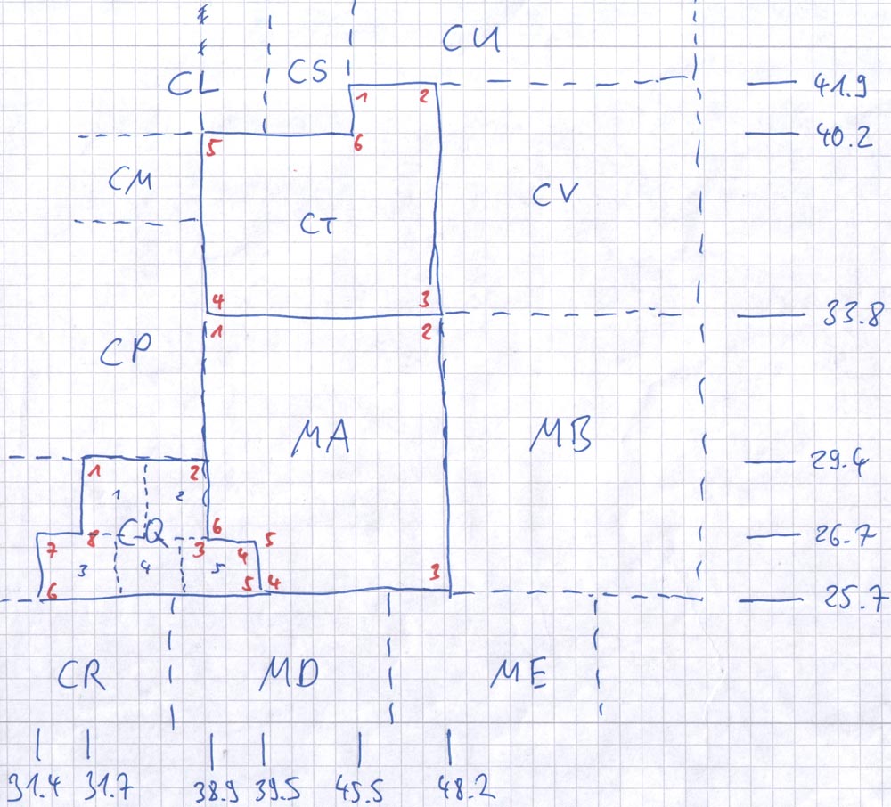
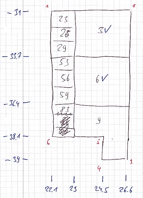
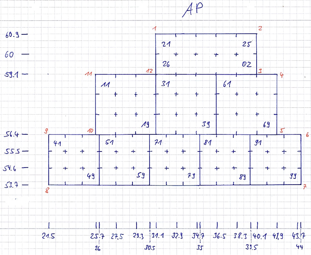
I drew the outer boundaries on a sheet of graph paper, then numbered all corners in clockwise direction starting with the most top left corner. Next I drew scales for longitudes and latitudes on the sides of the squares and marked them accordingly. I subdivided them into smaller units to get the corner coordinates and boundaries of the sub squares. Finally I drew the sub squares and named them accordingly.
When adding large squares to the repository, I started with the outer boundaries. I wrote the latitudes for the corners into the table, then the longitudes by reading them from the scale on the drawing. I repeated this for each sub square and if necessary for their sub squares.
In the beginning, these sketches were rough, but I improved the procedure over time and ended up rendering vector graphics for some squares. I also used Google Earth to depict the squares and analyze them by measuring gaps and adding sub squares step by step.
Software Design The rough architecture of the program
The heart of the program used to be the base library written in Hypertext Preprocessor (PHP). It contains the base data for all squares in the form of CSV files, the data model, a repository and a factory.
The data model describes the properties and behavior of squares and contains all necessary calculations. The repository is responsible for reading from the CSV files and transforming the data into appropriate data objects for further use. The factory is the main entrance point to the library. It is responsible for searching for the requested square within the repository and returning it to the client.
The user interface is a HTML5 web application originally written in PHP using a MVC framework, which I developed for personal projects. The design of the user interface was created using Twitter's Bootstrap, a ready-to-use CSS framework and lessphp, a LESScompiler written in PHP.
After several forced PHP updates by my provider I ran repeatedly into trouble with weird changes to the language. Many parts of my framework broke on OOP level and the poor UTF-8 support in PHP finally broke my neck. And since I was growing more and more tired of this fundamentally broken language, I finally decided to move the whole service to C# using ASP.NET MVC5 in 2015.
 Naval Grid Calculator
